Neutron Imaging Facility

Neutron Radiography

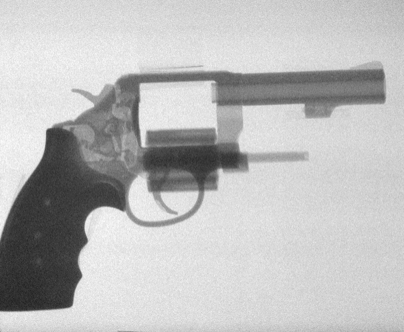
Neutron radiography is a powerful non-destructive imaging technique for the internal evaluation of materials or components. It involves the attenuation of a neutron beam by an object to be radiographed, and registration of the attenuation process (as an image) digitally or on film.

Neutron radiography is similar in principle to X-ray radiography, and is complimentary in the nature of information supplied. The interactions of X-rays and neutrons with matter are fundamentally different, however, forming the basis of many unique applications using neutrons (see Neutron and X-Ray Mass Attenuation Coefficients for the Elements graph below). While X-rays interact with the electron cloud surrounding the nucleus of an atom, neutrons interact with the nucleus itself.

Example Application of Neutron Radiography:

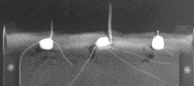
The 0.38 cm thick concrete specimen in the figure below was cut from a 10-cm diameter cylinder that had been loaded to a 3000 micro-cm/cm strain, just beyond its peak stress of 39 MPa. The specimen was impregnated with a Gadolinium Nitrate contrast agent prior to neutron imaging.

Micro-Cracks in Concrete
Images courtesy of H. Aderhold, Cornell University
X-radiograph of the specimen prior to impregnation with contrast agent. Using this technique, cracks – being empty spaces – should appear as black lines.
Small fractures (microcracks) that were filled with the contrast agent become visible and appear as white lines on the neutron radiograph.

NCSU Neutron Imaging Facility (NIF)

The Neutron Imaging Facility is installed at beamport #5 of the PULSTAR reactor, which provides a nominal source flux of 2.5×10¹² n/cm2/sec at 1 MW. The beam is collimated and filtered with 12 inches of single crystal sapphire.

The current aperture is a 1.44”x1.75” (1.8” effective diameter) rectangular cross section opening in a BORAL plate, which yields an L/D ratio of ~140 at the 6.5 meter imaging plane (see table of NIF Parameters below). The resolution of the system is ~ 33 microns for conventional radiographic film. Measurements using ASTM standards show that the NIF achieves a beam quality classification of IA.

NIF Cave with Thompson Tube installed.
Neutron Imaging Facility Parameters
Parameter Value
Neutron Flux 1.8×10⁶ to 7×10⁶ n/cm2/sec
TNC ~ 70%
N/G 4.43×10⁴ to 1.34×106 cm-2mR-1
L/D variable 100 to 150
Divergence ~2.29º
2 mil Gold-Cd Ratio ~450
Scatter Content ~1.8%

The neutron imaging beam diverges to a ~22″ diameter spot at the 6.5 meter imaging plane, allowing for uniform exposure of 14″x17″ film cassettes. The imaging cave is fully accessible to personnel while the beam shutter is closed, allowing for the setup of experiments.

Imaging Techniques

Imaging techniques available include conventional film, molecular phosphor digital imaging plates, and real-time Micro-Channel Plate and Thompson Tube imaging systems. Neutron tomographic measurement may be made utilizing a motorized sample positioning system in concert with realtime imaging systems.

Film:
  • Up to 14” x 17” using Gadolinium converter screen and vacuum cassette.
  • Maximum resolution ~33 microns.
  • The typical film radiograph can be completed in ~5 minutes resulting in an average film density of 2.
Molecular Phosphor Digital Image Plates:
  • Gd2O3 images plates.
  • Maximum resolution ~ 100 microns.
  • Linear dynamic range over 5 decades.
  • Reusable.
Micro-Channel Plate (MCP) Imaging System:
  • 15 mm diameter effective imaging area.
  • Maximum Resolution ~ 30 microns.
  • Maximum speed = 30 frames per second (fps).
  • Current CCD resolution = 2 megapixels.
Thompson Tube Imaging System:
  • 9 inch diameter effective imaging area.
  • Maximum Resolution ~ 200 microns.
  • Maximum speed = 30 frames per second (fps).
Tomography System:
  • Parallel beam 3D tomography.
  • Horizontal and Vertical Translation controlled by stepper motor and a Servo Feedback Rotatory Stage.
  • MCP and Thomson Tube detector system.
  • Time for 180 views with 512 frame averaged~ 2hour and 30 min.
  • Resolution depends on number of views taken.
  • Reconstruction using Filtered Back Projection and Statistical Techniques.

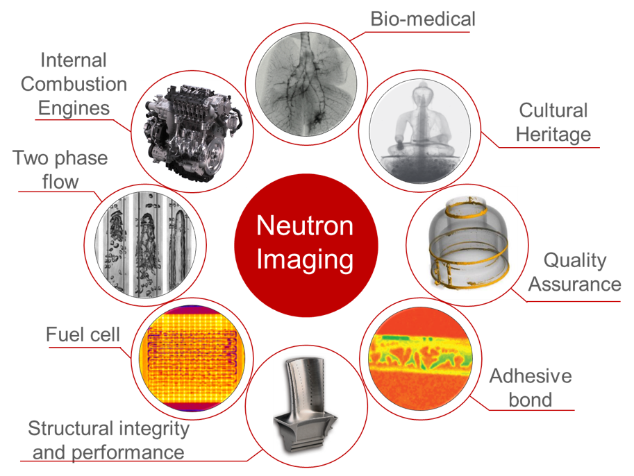
Example Imaging Applications

Soybean roots in-situ in soil column.
Water Distribution in PEM Fuel Cell stack.


Stress Cracks in Gun Barrel.

Additional Applications:

  • defects in silicon nitride (Si3N4) ceramics
  • imaging A/C refrigeration components for behavior of lubricating & cooling oils
  • detection of corrosion and entrapped moisture in mechanical structures
  • studying disbonding of carbon fiber composites (CFC’s)
  • measuring boron concentrations in shielding materials
  • measuring effectiveness of moisture repelling agents in building materials
  • imaging shock waves in gases
  • analysis of distribution of electrotransported hydrogen in palladium
  • quantitative evaluation of nuclear fuel pin structural features
  • microlocalization of boron after administration of paraboronphenylalanine to athymic mice carrying grafted human glioma.
  • imaging fluid spray patterns and dynamics
  • imaging of wetting front instabilities in porous media

Related Publications

Please contact the Manager of Nuclear Services if you are interested in learning more about applications of neutron imaging.